Pressure transmitters

1000 characters left
Обработка персональных данных включает согласие с Пользовательским соглашением и Политикой конфиденциальности и Вы принимаете их условия.

A pressure transmitter (hereinafter - ПД) is a primary measurement device intended for continuous conversion of the measured value into an analog output signal. PTs are used in pressure gauges which, in their turn, are applied for the operation in the systems of automatic control, regulation and managing of technological processes in various industrial areas.

Manufactured in accordance to TC 4212-002-59541470-2009

Использование Pressure

Measurement ranges:

  • pressure difference (ДД) — 1.6 kPa...16 MPa;
  • excess pressure (ДИ) - 40 kPa...25 MPa;
  • absolute pressure (ДА) — 10 kPA...16 MPa;
  • hydrostatic pressure (ДГ) — 40 kPa.. 250 kPa.

PTs use load cell transducers (sensors) on the basis of silicon resistive strain gauges on a sapphire membrane “Silicon on sapphire” (КНС)

A PT has several structural designs: flanged design, choke design with a liquid, choke design without a liquid, special design (choke, flanged).

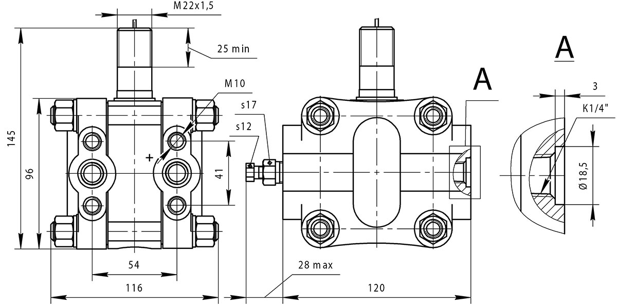
Flanged pressure transmitters have a measurement&transducing body frame in the assembly with flanges. The flanges provide for a process connection on the thread K1/4 or through an installed valve (globe valve) block. The body frame choke has a thread M22X1.5.

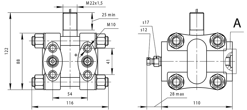
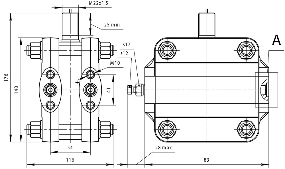
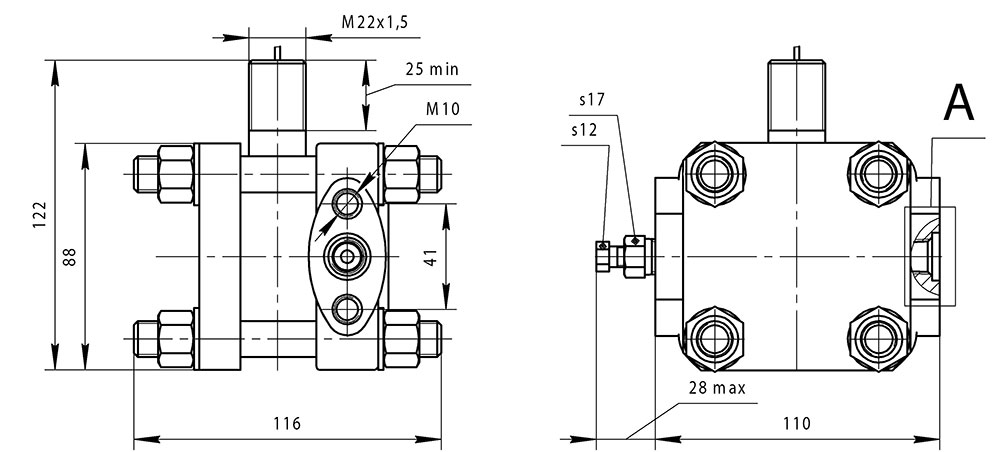
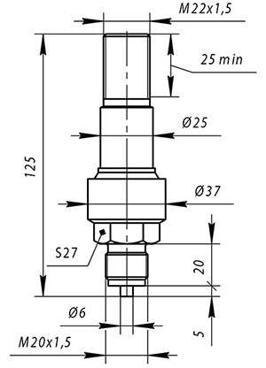
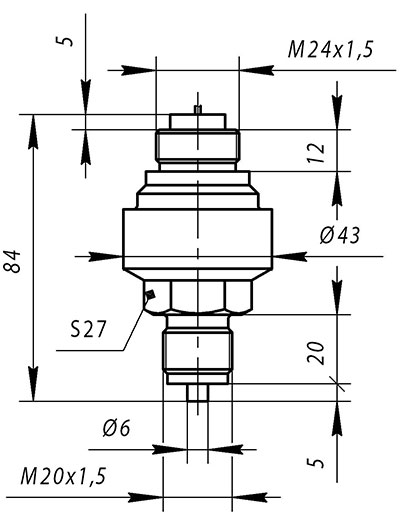
The ПД choke design with a liquid is made as a single measurement and transducing body frame. The body frame consists of an isolating membrane protecting a load cell transducer from aggressive media. The measured value is transmitted from the membrane to a sensitive element through the liquid filled into the internal cavity. The body frame provides for a process connection on the thread M20X1.5 or through an installed valve (globe valve) block. The body frame choke has a thread M22X1.5.

The ПД choke design without a liquid is made as a single measurement and transducing body frame. The measured value is directly transmitted to a sensitive element. The body frame provides for a process connection on the thread M20X1.5 or through an installed valve (globe valve) block. The body frame choke has a thread M22X1.5.

The special version of pressure transmitters can be made in compliance with any of the aforementioned version different in terms of process connection and the thread on the choke.

ПД electric supply is implemented by D.C. of not more than 1.5 mA.

The output signal range is from 90 mV to 400 mV depending on the model.

The ПД ingress protection rating corresponds to the group IP65 under GOST 14254.

Internal closed PT cavities are filled with the liquid PDMS-6 under GOST 13032-77. For the version with code "-K" - liquid ПЭФ-70/110 under TC 6-02-1072-76.

ДА, ДИ transmitter product range

Measured value Structural design Model Measuring limit
(ML)
Permissible overload pressure Weight, kg, not more
kPa MPa MPa
Absolute pressure (ДА) Flanged 2020 10 - 25 3,4
2030 40 - 25
2040 250 - 25
Choke version without liquid 2041 600 - 1 0,4
2051 - 2,5 4
2056 - 6 9
2061 - 16 25
Choke version with liquid 2040м5 600 - 1 0,5
2050м5 - 2,5 4
2056м5 - 6 9
2060м5 - 16 25
Excess pressure (ДИ) Choke version without liquid 2131 100 - 0,2 0,4
2141 600 - 1
2151 - 2,5 4
2156 - 6 9
2161 - 16 25
2171 - 100 110
Choke version with liquid 2140м5 600 - 1 0,5
2150м5 - 2,5 4
2156м5 - 6 9
2160м5 - 16 25
Special choke version with liquid 2140м 600 - 1 0,4
2150м - 2,5 4
2156м - 6 9
2160м - 16 25
2166м - 100 110
2152 - 2,5 4 1,4
2162 - 16 25
2172 - 60 70
2173 - 60 70 2,2

ДД, ДГ transmitter product range

Measured value Structural design Mode Measuring limit Maximum permissible operating excess pressure, MPa Weight, kg, not more
kPa MPa
Pressure difference (ДД) Flanged 2410 1,6 - 4 10
2412 2,5 - 6 5
2414 4,0 - 6 5
2420 10 - 10 4,6
2430 40 - 25
2434 40 - 40
2440 250 - 25
2444 250 - 40
2450 - 1,6 25
2450 - 2,5* 25
2460 - 16 25
Hydrostatic pressure (ДГ) Special flanged 2530 40 - 4 8
2540 250 -
*— *— temperature range equal to 70 °С (for example, temperature range from minus 20 °С up to plus 50 °С or from 0 °С up to plus 70 °С).

Metrological characteristics and output signal characteristics

Parameter Structural design Value
Output signal range at the D.C. power supply not less than 1.5 mA, mV choke version with a ML 100 kPa 90...200
choke version with a ML 600 kPa 150...400
all others 180...400
Resistance of power supply circuits and output signal, kOm choke version 3,5...4,85
flanged version 4,5 ± 0,35
Non-linearity of output signal, %, not more choke version 0,5
flanged version 1,0
Parameter Model Accuracy code
А0 А А1 В
Output signal variation, %, not more all 0,1 0,2
Change of U0 and UД, caused by the change of T for every 10 °С, %, not more all 1
Change of U0 and UДof ДД и ДГ transmitters, flanged version, caused by the change of Pизб на 1 МPA in the measurement range Pизб, %, not more 2410 0,125 0,2
2412, 2414 0,12 0,2
2420 0,04 0,08
2430, 2434, 2440, 2444 0,012 0,025 0,025
2450, 2460 0,012 0,025 0,025
2530, 2540 0,08

Note:

U0 — initial output signal value;

T — ambient temperature;

UД — output signal range;

Pизб — bilateral excess pressure.

Models 2412, 2414

 Models 2412, 2414

Models 2420, 2430, 2434, 2440, 2444, 2450, 2460

 Models 2420, 2430, 2434, 2440, 2444, 2450, 2460

Model 2410

 Model 2410

Models 2020, 2030, 2040

 Modelsи 2020, 2030, 2040

Models 2031, 2041, 2051, 2056, 2061, 2131, 2141, 2151, 2156, 2161, 2171

 Models 2031, 2041, 2051, 2056, 2061, 2131, 2141, 2151, 2156, 2161, 2171

Models 2040м5, 2050м5, 2056м5, 2060м5, 2140м5, 2150м5, 2156м5, 2160м5

 Modelsи 2040м5, 2050м5, 2056м5, 2060м5, 2140м5, 2150м5, 2156м5, 2160м5

Models 2140м, 2150м, 2156м, 2160м, 2166м

 Models 2140м, 2150м, 2156м, 2160м, 2166м

Models 2152, 2162, 2172

 Models 2152, 2162, 2172

Model 2173

 Model 2173

Models 2530, 2540

Models 2530, 2540

Materials contacting with operating media

Material code Material Applicability
membranes body frame parts contacting with an operating fluid of sealings as a part of a body frame*
02 Alloy 36НХТЮ Steel 12Х18Н10Т, replacer — 12Х18Н9Т, 08Х18Н10Т

rubber ring НО-68-1 (or 7-В-14);

for the version with the code "-К" — ИРП-1136

for all structural designs
06 Alloy 06ХН28МДТ Alloy 06ХН28МДТ, replacer — 10Х17Н13М2Т - only for the choke version with liquid
09 Titanium alloy Titanium alloy - only for the choke version without liquid
11 Titanium alloy Steel 12Х18Н10Т, replacer — 12Х18Н9Т, 08Х18Н10Т
*— only for the flanged version.


Parameter Value
Average service life providing the measured medium is non-aggressive to applicable materials, years, not less 16
Mean time to failure, hours, not less 250000
The quantity of withstand cycles of alternating pressure or exhaustion changing by not more than 50% of the transmitter change limit 20000
The transmitters are resistant towards ambient temperatures in the range, °С -50…+90
Ambient temperatures operating range, °С -40…+80
-25…+80 — for the versions with the code "-К"

Warranty liabilities

Parameter Value
Warranty operating life, months 36 months since the commissioning date but no more than 42 months since the date of manufacture

Contents of delivery

Name Number
Pressure transmitter 1
Data Sheet 1

Designations at the order

ПД 2420 А 02 К ТУ 4212-002-59541470-2009
1 2 3 4 5  6
  1. Name.
  2. Model.
  3. Accuracy code (according to the table "Metrological and output signal characteristics").
  4. Code of materials contacting with operating media.
  5. The code "K" is entered at the order of a transmitter for the operation with the gas oxygen and oxygen-containing gaseous mixtures.
  6. Technical conditions.

Pressure transmitters

wait Item successfully added.
Proceed to checkout?
1000 characters left
Обработка персональных данных включает согласие с Пользовательским соглашением и Политикой конфиденциальности и Вы принимаете их условия.