Multifunctional controlled measuring unit МИР-7200

1000 characters left
Обработка персональных данных включает согласие с Пользовательским соглашением и Политикой конфиденциальности и Вы принимаете их условия.

Used for data conversion and transmission from the analog flow rate, pressure, level, temperature and other unit sensor.

  • Compatible with all types of output analog signal sensors;
  • Indicates measured parameters on the four-digit seven-segment display ;
  • alarm for the threshold value excess of the measured parameter ;
  • relay control;
  • remote configuration and data exchange on RS-232 or RS-485, Modbus-RTU protocol;
  • extensive temperature range −60...+60 °С for DIN execution.

Produced according to  technical conditions  EI.72.00.000ТU

Использование Secondary equipment

The heat controller has one universal measuring input and operates as the normalizing converter to measure analog signals:

  • from resistance temperature converters with nominal static characteristics (hereinafter referred to as NSCs) 50М, 53М, 100М, 50П, 100П, Pt100 according to GOST  6651-2009 (the connection scheme is two-, three- or four-wire);
  • from thermocouples of  ТХА(К), ТХК(L), ТПП(S), ТПР(В), ТЖК(J), ТВР(A-1) types according to GOST Р 8.585-2001;
  • DC voltage within ranges of  0…20 mV, 0…50 mV, 0…100 mV, 0…1000 mV;
  • DC powers within ranges of  0…5 mА, 4…20 mА, 0…20 mА;

resistance within the range of 0…320 ohm.

en 32 p1

Functional circuit

Functional circuit 

The technological controlling measuring unit:

  • measures analog signals from flow rate, level, temperature and other sensors (the VP module); 
  • controls the measured parameter according to the two-point (relay) rule (the MK module);
  • calculates the square root from the measured parameter (MKM unit);
  • displays the current value of the measured parameter at the built-in LED digital display (the MIK module);
  • forms uniformed output signals of DC power within ranges of  0…5 mА, 4…20 mА, 0…20 mА to record the measured data or to control actuation devices (the MAV module);
  • displays measured values on the personal computer (hereinafter referred to as the PC) and adjusts the controller to the PC via the RS-485 or RS-232 interface (the MI module);
  • feeds sensors with the uniformed output signals or other devices via the current loop from the built-in power source (BPS).
Controlling logics

The measuring controller may include up to five galvanically isolated commutation channels.

Commutation is done using:

  • relay;
  • optical relay;
  • optical bidirectional triode thyristor.

Controlling signals are programmably calculated and depend on current states of the relay, the value of the measured input signal, fixed set-point, hysteresis values and logics of the commutation channel operation.

For each commutation channel, you may determine the response logics after receipt of signals from each threshold device.

Controlling logics

Key technical characteristics

ParameterValue
A.C. supply voltage range, V 85…265
A.C. supply voltage frequency, Hz 49,5…50,5
Capacity consumed from the AC system, V·А not more than 6,5
Structural design (by order)

DIN version—plastic body frame with a DIN or wall mounting option

Version 01 — plastic body frame to be panel board-mounted

Version 02 — metal body frame to be panel board-mounted

Weight, kg

not more than 0,4—for 01, DIN version

not more than 1,0—for version 02

Technical characteristics of the measurement channel

ParameterValue
Input resistance of the measurement channel at connection of the unified current signal source, ohm 50
Input resistance of the measurement channel at connection of the voltage source, kOm not less than 100
Connection scheme of the resistance temperature converter 2, 3, 4 wired
Length of the connection line for resistance temperature converters at the line resistance of not more than 15 Om, m not more than 100
Length of the connection line for thermocouples at the line resistance (the thermocouple cable) of not more than 100 Om, m not more than 20
Length of the connection line for the unified DC signal at the line resistance of not more than 5 Om, m not more than 100

Technical characteristics of the analog output

ParameterValue
Functional relation of the output DC power signal from the input measured parameter (selected by the user).

linear,

root

Basic root percentage error limit , % ± 0,1
Current output load resistance for the range of 0…5 mА, Om not more than 1500
Current output load resistance of 4…20 mА, 0…20 mА, Om not more than 400

The current output may be used as a DC source within the range of 0…20 mА, set with accuracy of 0,01mА (the fixed current mode).

Technical characteristics of the built-in power source

ParameterValue
Output voltage, V 24
Output voltage deviation,% not more than 0,2
Output voltage pulsation amplitude, V not more than 0,1
Maximum load current, mA 26
Tripping event current, mA not more than 40
Short circuit current, mA not more than 20
Change of the output voltage caused by change of the ambient air temperature, % not more than 0,1
Change of the output voltage caused by vibration effect, % not more than 0,2

Technical characteristics of RS-485 and RS-232 interfaces

ParameterValue
Interface exchange speeds, Kbit/s
(chosen by the user)
2,4; 4,8; 9,6; 19,2; 38,4; 57,6; 115,2
IP address range (chosen by the user) 1…255
Exchange protocol MODBUS RTU

Cable length, m:

RS-485 interface;

RS-232 interface

not more than 1200

not more than 10

The built-in load resistance of 20 ohm is used for the work as a terminal unit (except execution of 02).

Connection of the controlling measuring unit with RS-485 interface may connected directly to the PC via the USB interface using the ЭнИ-402 interface converter.

Recommendations on RS-485 network expansion.


Type of the primary converter (sensor)DesignationMeasurement range, °СRange of converter resistance changes according to НСХ, Ом2)δц1), %δт1), %

50М, R100 / R0 = 1,42603)

α = 0,004264)

Cu65 –50…+200 39,35…92,62 ± 0,2 ± 0,25

53М, R100 / R0 = 1,4260

α = 0,00426

Cu63 41,71...98,16

100М, R100 / R0 = 1,4260

α = 0,00426

Cu61 78,70…185,20

50М, R100 / R0 = 1,4280

α = 0,00428

Cu85 39,23…92,80

53М, R100 / R0 = 1,4280

α = 0,00428

Cu83 41,58…98,37

100М, R100 / R0 = 1,4280

α = 0,00428

Cu81 78,46…185,60

50П, R100 / R0 = 1,3910

α = 0,00391

PtH5 –50…+600 40,00…158,56

100П, R100 / R0 = 1,3910

α = 0,00391

PtH1 80,00…317,11

Pt100, R100 / R0 = 1,3850

α = 0,00385

Ptb1 80,31…313,71
Type of the primary converter (sensor)DesignationMeasurement range, °СRange of converter resistance changes according to НСХ, Ом3)δц1), %δт1), %
ТЖК (J)5) FC –50…+1100 –2,431…+63,792 ± 0,56) ± 0,76)
ТХК (L) HE –50…+600 –3,005…+49,108
ТХА (K) HA –50…+1300 –1,889…+52,410
ТПП (S) PP 0…1700 0,000…17,947
ТПР (B) Pr 300…1800 0,431…13,591
ТВР (A-1) BP 0…2500 0,000…33,640
Type of the primary converter (sensor)DesignationMeasurement range, °СInput resistance, kiloOhm, not less thanδц1), %δт1), %
Напряжение U20 0…20 100 ± 0,2 ± 0,25
U50 0…50
U100 0…100
U1V 0…1000
Type of the primary converter (sensor)DesignationMeasurement range, °СImput resistance between I+ и I- terminals, mV, not more thanδц1), %δт1), %
Ток t05 0…5 500 ± 0,2 ± 0,25
t420 4…20 2000
t020 0…20 2000
Type of the primary converter (sensor)DesignationMeasurement range, °СCurrent through measured resistance, mА2)δц1), %δт1), %
Resistance rr 0…320 0,2 ± 0,2 ± 0,25

1) δц, δт — are limits basic percentage error for digital and current outputs.

2) Reference paramenter.

3) R100 и R0 — are values of resistance from НСХ at 100 and 0 °С, respectively.

4) α — are the temperature coefficient of resistance temperature converter.

5) Brackets contain types of thermocouples according to МЭК 60584-3.

6) Taking into account the error of the cold junction temperature compensation error.

The digital channel of the controller converts the measured signal into:

  • the digital code for displaying values;
  • digital values transmitted via the MODBUS protocol by RS-485 or RS-232 interfaces2.

DIN version

DIN version 

1, 2, 3, —status displays of commutation channels;

4 — Connector for the RS-485 (RS-232) interface;
5 — Terminal block for connection of the sensor;
6 — Terminal block for connection of the current output;
7— Terminal block for connection of the power supply voltage and earthing;
8— Terminal block for connection of the 24V power source;
9, 10, 11— Terminal blocks for connection of commutation channels;
12 — main four-digit LED display «Data»;
13 — additional four-digit LED display «Mode»;
14— button «left»;
15— button «output»;
16— button “right”;
17— button “input”;
18— warranty label.

The DIN version with five commutation channels

The DIN version with five commutation channels 

1, 2, 3, 4, 5 —status displays of commutation channels;
6— “output” button;
7— “left” button;
8 — Terminal block for connection of the sensor;
9— Terminal block for installation of the connection mode jumper;
10 — Terminal block for connection of the RS-485 interface;
11 — Terminal block for connection of the built-in 120 Om resistor;
12— Terminal block for connection of the power supply voltage and earthing;
13, 14, 15, 16, 17— Terminals blocks for connection of commutation channels;
18 — main four-digit LED display “Data”;
19 — additional four-digit LED display “Mode”;
20— button “input”;
21— button “right”;
22— warranty label.

Version 01

 Version 01

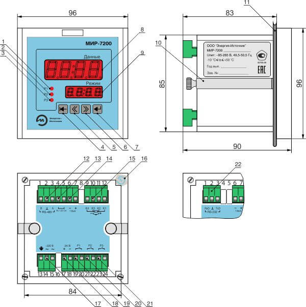
1, 2, 3 —status displays of commutation channels;
4— button “output” ;
5— button “left” ;
6— button “right”;
7— button “input”;
8 — main four-digit LED display “Data”;
9 — additional four-digit LED display “Mode”;
10 — C-clamp with a screw;
11 — screen;
12 — Terminal block for connection of the RS-485 interface;
13 — Terminal block for connection of the built-in 120 Om resistor;
14 — Terminal block for connection of the current output;
15 — Terminal block for connection of a sensor;
16— Warranty label;
17— Terminal block for connection of the power supply voltage and earthing;
18— Terminal block for connection of the 24 V power source;
19, 20, 21— Terminal blocks for connection of commutation channels;
22 — Terminal block for connection of the RS-232 interface.

Version 02

 Version 02

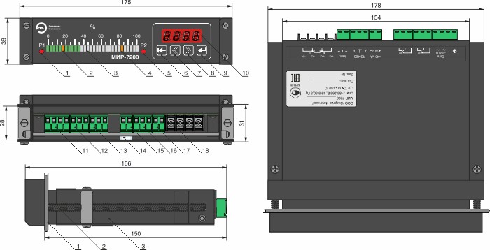
1, 5 —status displays of commutation channels;
2, 4 — set-points of threshold devices;
3 — linear analog discrete LED three-colour display;
6— button “output”;
7— button “left”;
8— button “right”;
9— button “input”;
10 — four-digit LED display;
11— connector for the power supply voltage and earthing;
12, 13— connectors for commutation channels;
14— warranty label;
15— connector for the 24V power source;
16 — connector for the RS-485 interface;
17 — connector for the current output;
18 — Terminal block for connection of the sensor.

Functions of displays

Operational modeDisplay “Data”Display “Mode”
measurement number values of the measured parameter type of the input signal or the primary converter
Messages about the status of the controller in cases of emergency Number value for response set-points of one commutation channel
configuration Names of the menu points Parameter values

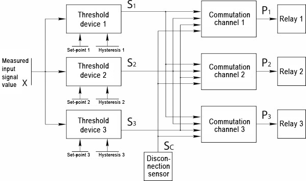
LED indicators «Р1»; «Р2»; «Р3», «Р4», «Р5» on the front plate of temperature controller display the state of the commutation channel relays:

  • the display is on— the relay is on;
  • the display is off— the relay is off.

Functions of buttons

ButtonFunction
 16 7 1 — switching from the configuration mode to the measurement mode
—  the configuration mode: back to the top menu from the submenu
—  the configuration mode:cancellation of the parameter value change mode
 16 7 216 7 3 — the configuration mode: selection of the changed parameter (the menu point)
— the configuration mode: selection of parameter value to the backward or forward directions, respectively
 16 7 4 — switching of the controller to the configuration mode
— the configuration mode: switching from the submenu to the menu
— the configuration mode: switching to the parameter value change mode
— the configuration mode: record into the memory of the changed parameter mode


DIN version

DIN version 

DIN version with five commutation channels

DIN version with five commutation channels  

Version 01

Version 01 

Version 02

Version 02 


ParameterValue
Ambient temperature, °С

−10...+50

−60...+60 for DIN version with five switching channels

In terms of climatic effect resistance at operation corresponds to the version group, under GOST R 52931–2008 С3
In terms of mechanical impact resistance at operation corresponds to the version group, under GOST R 52931–2008 L3
Ingress protection level, under GOST 14254–96

IP20

IP54 for the versions 01 and 02 on the front panel side

Warranty liabilities

ParameterValue
Warranty operating life, months 36 months since the commissioning date but no more than 42 months since the date of manufacture

Contents of delivery

NameDesignationNumberNote

Multifunctional controlling measuring unit

МИР-7200

ЭИ.98.00.000

ЭИ.133.00.000

ЭИ.138.00.000

ЭИ.165.00.000

1 On order
Data Sheet ЭИ.72.00.000ПС 1  
User manual ЭИ.72.00.000РЭ 1 For the batch of controllers (20 pcs) delivered at the same address
Software CD   1 If there is the RS-232 or RS-485 interface for the batch of controllers (20 pcs) delivered at the same address
RS-232 cable modem
DB9F-DB9M
1 If there is the RS-232 interface
RS-232 cable adapter ЭИ.178.10.000 1 for versions 01 and 02 if there is the RS-232 interface
DP-9C Case   1 For the DIN if there is the RS-485 interface
DB-9F connector (socket connector)   1
Socket (2 contacts) 2EDGK-5.0-02P 1 For the version 02 if there is the built-in power source
Socket (2 contacts) 2EDGK-5.0-02P 1 For the version 02 if there is the current output
Socket (3 contacts) 2EDGK-5.0-03P 1 For the version 02 if there is RS-232 or RS-485 interface
Socket (3 contacts) 2EDGK-5.0-03P 2 For the version 02 if there are commutation channels
Socket (4 contacts) 2EDGK-5.0-04P 1 For the version 02
ЭнИ-402 interface converter     On order
DIN rail NS35\7,5 m On order

Designations at the order

МИР-7200Г312102-(0…100)%360ГП
1 2 3 4 5 6 7 8 9 10 11

1. Name.

2. Version of commutation channels:

  • А — the optical bidirectional triode thyristor — AC commutation 0,3 А, 250 V;
  • Б — the optical relay — the DC and AC commutation 4,5 А, 20 V;
  • В — the optical relay — the DC and AC commutation 240 mА, 400 V;
  • Г — the relay — the DC commutation of up to 15 А of voltage of up to 30 V, but not more than 240 W or the AC commutation of up to 15 А of voltage of up to 250 V, but not more than 2770 V·А;
  • no symbol— no commutation channels.

3. Version according to the type of measured signals:

  • 1 — DC power and voltage;
  • 2 — resistance and signals from resistance temperature converters (and DC powers for the DIN version with five commutation channels);
  • 3 — DC power and voltage, signals from resistance converters and signals from thermocouples.

4. Presence of the current output:

  • 0 — no current output;
  • 1 — current output.

5. Presence of the interface:

  • 0 — no interface;
  • 1 — иthe RS-232 interface;
  • 2 — the RS-485 interface.

6. Presence of the built-in power source:

  • 0 — no built-in power source;
  • 1 — built-in power source.

7. Constructive version:

  • DIN — version of the body with installation on the DIN rail or on the wall;
  • 01 — version of the body with installation into the screen;
  • 02 — version of the body with installation into the screen.

8. Number of commutation channels (for the DIN version only):

  • no symbol — three commutation channels;
  • 5 — five commutation channels.

9. Version of the controller's front panel, the measurement range, measuring units (for the version 02):

  • (0…100) %;
  • (0…100) мВ;
  • (0…100) °С;
  • (0…20) mА;
  • (0…320)Om.

10. Additional technological run-in is up to 360 hours.

11. Presence of the state calibration.

Note — The version with five commutation channels is possible only in the МИР-7200-G-2-0-2-0-DIN-5 configuration.

Multifunctional controlled measuring unit МИР-7200

Description of the meter-controller multi-function МИР-7200
wait Item successfully added.
Proceed to checkout?
1000 characters left
Обработка персональных данных включает согласие с Пользовательским соглашением и Политикой конфиденциальности и Вы принимаете их условия.