Power supply units with a root-extracting function БПКМ

Category: Power supplies

1000 characters left
Обработка персональных данных включает согласие с Пользовательским соглашением и Политикой конфиденциальности и Вы принимаете их условия.

Power supply for non-explosion-proof sensors with unified current signals 4…20 mA, 0…20 mA, 0…5 mA, as well as for the functional conversion of these signals into the levels 4…20 mA, 0…20 mA, 0…5 mA with a root-extracting dependence.

  • Overload and short circuit protection;
  • Output voltages 24/36 V;
  • Root-extracting function;
  • Indication of channel operation;
  • DIN-, wall - or panel board-mounted

Manufactured in accordance to TC 4218-002-51465965-2010

Использование Functional equipment

The unit consists of a stabilized D.C. power supply source with an output voltage 36 V (or 24V - by the customer’s order) with the overload&short circuit protection device and a root-extracting circuit. The electric protection circuit is intended to protect a power supply unit against overloading and short circuits in a load. The power supply unit automatically switches to the operating mode after overload or short circuit elimination. The root-extracting surface provides for an output signal proportionate to the input signal square root.

Key technical characteristics

ParameterValue
A.C. supply voltage range, V 187...242
A.C. supply voltage frequency, Hz 49...51
Consumed power, V×А 7,0
D.C. output supply source voltage (by order), V 24, 36
Maximum load current, mA 55
Possible variants of input unified current signals (by order), mA 0...5, 0...20, 4...20
Possible variants of output unified current signals (by order), mA 0...5, 0...20, 4...20
Tripping event overload current, mA not more than 75
Short circuit current, mA not more than 45
Unit input resistance for a signal 0...5 mA, Om not more than 500
Unit input resistance for a signal 0...20 , 4...20 mA, Om not more than 200
Output channel circuits are intended for the work with the loads, Ohm, for the signal 0...20, 4...20 mA with the account of the communication line resistance not more tha 750
Output root-extracting channel circuits are intended for the work with the loads, kiloOhm, for the signal 0...5 mA with the account of the communication line resistance not more than
Resistance of the unit sensor communication line cables, Om not more than
Stabilization class of the supply source output voltage 0,2
The change of the supply source output voltage value at the maximum load current induced by the change in supply voltage within permissible limits, %, of the voltage nominal value not more than ±0,1
The change of the supply source output voltage value induced by the ambient temperature change within the range of -10 to +60 °С shall not exceed, %, of the supply source output voltage at the maximum load current for every 10 °С ±0,1
Supply source output voltage pulsation, %, of the voltage nominal value not more than ±0,1
The maximum permissible voltage pulsation value on the root-extracting channel input, %, of the measured voltage value ±0,2
Insulation strength between the input supply channel and output supply channel, V 1500
Insulation strength between the input supply channel and root-extracting channel, V 1500
Insulation strength between the input supply source channel and root-extracting channel, V 300
Structural design (by order) 
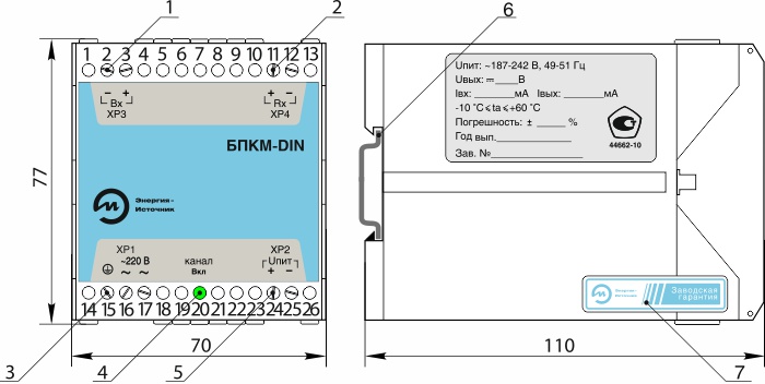
plastic body frame with a DIN or wall mounting option (version DIN)

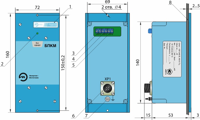
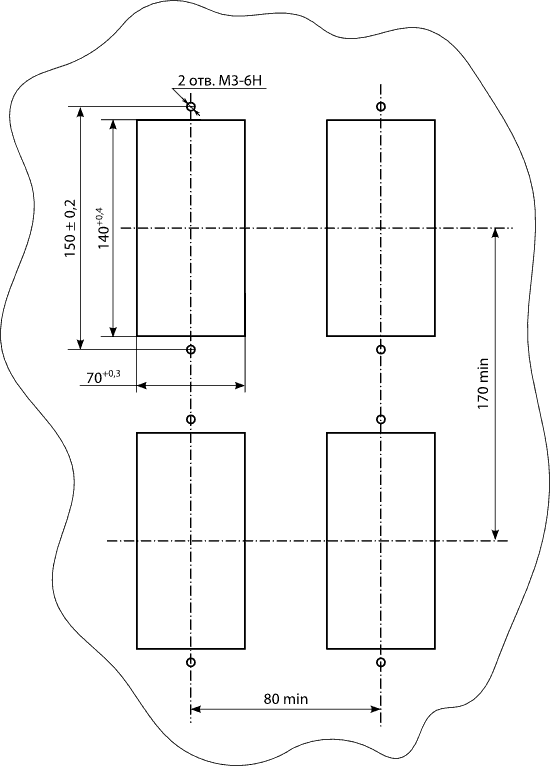
plastic body frame with a metal face plate with a panel board-mounting option (version 01)
Weight, g
for the version 01
for the version DIN
not more than 500
not more than 400


ParameterValue
Limits of permissible basic percentage error for the root-extracting channel, %, of the output signal change range at the input signal change:
from 0 to 5 %
from 5 to 100 %
±2
±0,15 или ±0,25 (by order)
Limits of permissible basic percentage error for the root-extracting channel induced by the change of the supply voltage within the set limits shall not exceed the limits of permissible basic percentage error for the root-extracting channel
Limits of permissible basic percentage error for the root-extracting channel induced by the change of the ambient temperature within the limits from −10 to +60ºС shall not exceed the limits of permissible basic percentage error for the root-extracting channel for every 10 °С
Limits of permissible basic percentage error for an output signal induced by the vibration action shall not exceed, %, the range of output signal change for the root-extracting channel ±0,2
Limits of permissible basic percentage error for an output signal induced by the vibration action shall not exceed, %, of the output voltage ±0,2
Calibration interval, year 2

БПКМ исполнение 01

БПКМ исполнение 01

1 — warranty label;
2 — LED indicating the channel operation;
3 — terminal block DG301-5.0-02P to connect the sensor supply voltage;
4 — кterminal block DG301-5.0-02P to connect the sensor current signal (input current signal);
5 — terminal block DG301-5.0-02P to connect the load (output current signal);
6 — connector 2РМ14КПН4Ш1В1 to connect supply voltage;
7 — grounding bolt;
8 — panel board.

Numbering of the contacts of the connector XP1 to connect the supply voltage (version 01)

Numbering of the contacts of the connector XP1 to connect the supply voltage (version 01)

Cut-off in a panel board

БПКМ version 01-shield Cutout

БПКМ DIN-version

БПКМ DIN-version

1 — terminal box DG301-5.0-02P to connect the sensor current signal (input current signal);
2 — terminal signal DG301-5.0-02P to connect load (output current signal);
3 — terminal box DG301-5.0-02P to connect supply voltage;
4 — LED indication of the channel operation;
5 — terminal box DG301-5.0-02P to connect the sensor supply voltage;
6 — DIN-rail;
7 — warranty label.


Unit БПКМ connection diagram, version 01, to the sensor with an output current signal 0...5 and 0...20 mA

Unit БПКМ connection diagram, version 01, to the sensor with an output current signal 0...5 and 0...20 mA

V1 — multimeter;
R1 — load resistance.

Unit БПКМ connection diagram, version 01, to the sensor with an output current signal 4...20 mA

Unit БПКМ connection diagram, version 01, to the sensor with an output current signal 4...20 mA

V1 — multimeter;
R1 — load resistance.

Unit БПКМ connection diagram, version DIN, to the sensor with an output current signal 0...5 and 0...20 mA

Unit БПКМ connection diagram, version 01, to the sensor with an output current signal 4...20 mA

V1 — multimeter;
R1 — load resistance.

Unit БПКМ connection diagram, version DIN, to the sensor with an output current signal 4...20 mA

Unit БПКМ connection diagram, version DIN, to the sensor with an output current signal 4...20 mAА

V1 — multimeter;
R1 — load resistance.

Unit check circuit

 Unit check circuit

R1 — resistor С2-29В-0.25-2.4 kOm ± 0,5 %;
R2, R6 — — reference resistance coil Р331 100 Om;
R3 — resistor С2-29В-0,25-649 Оm ± 0,5 %;
R4 — resistor С2-29в-0,25-1 kОm ± 0,5 %;
R5 — plug resistance Р4831, accuracy class 0,02 %.
R7 — resistor ПП3-40 1 kOm ± 10 %;
Т — lab transformer АОСН-20-220-75 Hz;
РА1 — мmultimeter РС5000 in the A.C. measurement mode;
РА2 — multimeter РС5000 in the A.C. measurement mode;
PV1 — multimeter РС5000 in the alternating voltage measurement mode;
PV2 — multimeter РС5000 in the direct voltage measurement mode;
PG — oscillograph С1-74;
SA1, SA2, SA4 — switches П2Е 13;
SA3.1, SA3.2 — rotary switch ПГ3-11П-2Н.


ParameterValue
Ambient temperature, °С -10...+60
In terms of climatic effect resistance at operation corresponds to the version group, under GOST R 52931–2008 С3
In terms of mechanical impact resistance at operation corresponds to the version group, under GOST R 52931–2008 L3
Ingress protection level, under GOST 14254–96::
version DIN
version 01
IP20
IP30

Гарантийные обязательства

ParameterValue
Warranty operating life, months 36 months since the commissioning date but no more than 42 months since the date of manufacture

Contents of delivery

NameDesignationNumberNote
БПКМ   1  
Data sheet, Operation manual   1  
ХР1 — socket 2РМ 14КПН4Г1В1 1 for the version 01
rail NS35\7,5 m by order

Designations at the order

БПКМ005420360,1501360ГП
1 2 3 4 5 6 7 8
  1. Name.
  2. Input signal range:
    • 005 — 0...5 mA;
    • 420 — 4...20 mA;
    • 020 — 0...20 mA.
  3. Output signal range:
    • 005 — 0...5 mA;
    • 420 — 4...20 mA;
    • 020 — 0...20 mA.
  4. Power supply source voltage, V.
  5. Limit of permissible basic percentage error, %*.
  6. Structural design:
    • DIN — version DIN;
    • 01 — version 01.
  7. Additional technological no-failure operating time 360 hours.
  8. State calibration.

* — error at the key characteristic area (within the input signal range from 5 to 100 %).

Power supply units with a root-extracting function БПКМ

Description power supply with corneillie (БПКМ)
wait Item successfully added.
Proceed to checkout?
1000 characters left
Обработка персональных данных включает согласие с Пользовательским соглашением и Политикой конфиденциальности и Вы принимаете их условия.