Use

Calibration signal source (calibrator) ЭнИ-201I


1000 characters left
Обработка персональных данных включает согласие с Пользовательским соглашением и Политикой конфиденциальности и Вы принимаете их условия.

A calibration signal source (hereinafter referred to as a calibrator) is a multifunctional microprocessor device intended for the reproduction of direct voltage and current precision values at calibration, verification and setting of measurement instruments in laboratory and industrial conditions.

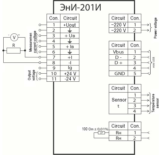
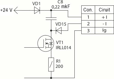
  • Reproduction of voltage and current precision value through two independent channels;
  • Reproduction (imitation) of thermal couple standard signals;
  • Built-in voltmeter to measure output signal values;
  • Thermal compensation of cold junction by means of a temperature sensor;
  • Built-in reference load resistor 100 Ohm;
  • Opportunity to make up calibrating tables;
  • Software allowing for the calibrator regulation and making up computer-aided calibration tables.

Manufactured in accordance with the technical conditions EI.120.00.000 TC

Использование Etc

The calibrator is the programmable voltage (-10...+100 mV, −1...+10 V) and current (0...5 mА, 0...20 mА, 4...20 mА) source. As for the number of reproducing channels, the calibrator is dual-channel. The voltage and current values are simultaneously and independently formed in the device and are terminated on the output terminals.

The calibrator has an opportunity to measure external voltage and current.

The calibrator is capable of reproducing the voltages of standard thermal couple types as well as of measuring the temperature using an external thermal couple. Cold junction thermal compensation is performed with the help of remote temperature sensor.

The calibrator consists of the built-in stabilized DC power source (the  output  voltage is 24 V) with the overload and short circuit protection device and galvanically separated from other circuits. The additional standard loading resistor for 100 Om ±0.01 % may be optionally included into the calibrator.  The resistor is connected to the terminals independent from circuits and located at the rear plate of the calibrator.

Voltage and current values are entered into and stored in the memory from the push-button keyboard located on the calibrator’s body frame.

The output voltage and current value in each range is stored and extracted from 100 points divided into 10 tables with 10 points each.

Key technical characteristics

ParameterValue
A.C. supply voltage range, V 187...242
A.C. supply voltage frequency, Hz 49...51
Consumed power, V×А 5
D.C. voltage output signal ranges −10...+100 mV, −1...+10 V
Ranges of a D.C. unified output signal, mA 0...5, 4...20, 0...20
Load resistance of the voltage reproduction output, kOm not less than 100
Analog output load resistance for the ranges of 4...20 mА, 0...20 mА, Ohm not more than 400
Analog output load resistance for the range of 0...5 mА, Ohm not more than 1500
Time of operating mode setting is not more than, min 60
Structural design plastic body frame
Overall dimensions, mm 226×70×196
Weight, kg 0,5

Technical characteristics of built-in supply source

ParameterValue
Nominal D.C. output voltage, V 24
Output voltage deviation from the nominal value, % not more than 0,5
Output voltage pulsation amplitude, V not more than 0,1
Load current, mA 25
Tripping event current, mA not more than 50
Short circuit current, mA not more than 20
Output voltage change induced by the ambient temperature change, % not more than 0,1
Output voltage change caused by vibration, % not more than


Range nameRangeLimits of permissible basic percentage error, %
Current generation 0...25 mА ±(0,015% GV* + 0,00125 mA)
Voltage generation -10...100 mV ±(0,015% GV* + 0,005 mV)
-1...10 V ±(0,015% GV* + 0,001 V)
Current change -25 ... +25 mA ±(0,015% MV** + 0,00125 mA)
Voltage measurement -100...+100 mV ±(0,015% MV** + 0,01 mV)
-10 ... +10 В ±(0,015% MV** + 0,001 V)

* – generated value.
** – measurable value.

ParameterValue
Limits of permissible complementary error induced by the ambient temperature change comparing with a normal value (23+2) °С up to any temperature within the operation temperature range not more than the limits of permissible basic percentage error, %
Limits of permissible complementary error caused by high humidity action not more than the limits of permissible basic percentage error, %
Limits of permissible complementary error caused by the supply voltage change comparing with the nominal value in the operating range not more than the limits of permissible basic percentage error, %
Calibration interval, year 1

Metrological characteristics of an additional built-in reference load resistor 100 Ohm

ParameterValue
Resistance deviation from a nominal value, %/td> not more than ±0,01
Resistance temperature coefficient, ppm/°C ±2,0
Long-term stability (at °C, 2000 ч), % ±0,005
Maximum operating voltage, V 300

External appearance and overall dimensions of ЭнИ-201I

External appearance and overall dimensions of ЭнИ-201I

1 — liquid crystal two-line indicator;
2 — keyboard of 16 buttons;
3 — connector 15EDGK-3.81-02P to terminate the generated voltage values;
4 — connector 15EDGK-3.81-02P to connect the measured voltage;
5 — connector 15EDGK-3.81-02P to connect the measured current;
6 — connector 15EDGK-3.81-03P to terminate the generated current values;
7 — connector 15EDGK-3.81-02P of the supply source;
8 — разъем для подключения сетевого кабеляconnector for a mains cable;
9 — power supply on tumbler;
10 — miniUSB for PC-connection;
11 — connector for an external temperature sensor;
12 — reference resistor terminals 100 Ohm (by the customer’s order);
13 — warranty label.

Connection diagram of ЭнИ-201I in the mode of sink current reproduction

Connection diagram of ЭнИ-201I in the mode of sink current reproduction

Connection diagram of ЭнИ-201I in the mode of source current reproduction

Connection diagram of ЭнИ-201I in the mode of source current reproduction

Connection diagram of ЭнИ-201I in the mode of voltage reproduction

Connection diagram of ЭнИ-201I in the mode of voltage reproduction

Current generator output cascade

Current generator output cascade


ParameterValue
Ambient temperature, °С +10…+40
In terms of climatic effect resistance at operation corresponds to the version group, under GOST R 52931–2008 В2
Ingress protection level, under GOST 14254–96 IP30

Warranty liabilities

ParameterValue
Warranty operating life, months 36 months since the commissioning date but no more than 42 months since the date of manufacture

Contents of delivery

NameDesignationNumberNote
Calibration signal source ЭнИ-201I ЭИ.180.00.000 1 in compliance with the order
Data Sheet ЭИ.120.00.000ПС 1  
Operation manual ЭИ.120.00.000РЭ 1  
Disc with software   1  
USB cable — miniUSB ЭИ.180.00.000ДО 1  
Mains cable ЭИ.180.00.000ДО 1  
Temperature sensor DS18B20 ЭИ.180.04.000 1  
Terminal board (3 contacts) 15EDGK-3.81-03P 1  
Terminal board (2 contacts) 15EDGK-3.81-02P 4  
Connector cable with “crocodile”-type clips ЭИ.180.05.000 2 by order

Designations at the order

ЭнИ-201ИR100360ГП
1 2 3 4
  1. Name.
  2. Availability of an additional built-in reference load resistor 100 Ohm.
  3. Additional technological no-failure operating time 360 hours.
  4. State calibration.

Calibration signal source (calibrator) ЭнИ-201I

Description: ЭнИ-201И Calibrator
wait Item successfully added.
Proceed to checkout?
1000 characters left
Обработка персональных данных включает согласие с Пользовательским соглашением и Политикой конфиденциальности и Вы принимаете их условия.