Six-channel measurement modules Эни-702I

1000 characters left
Обработка персональных данных включает согласие с Пользовательским соглашением и Политикой конфиденциальности и Вы принимаете их условия.

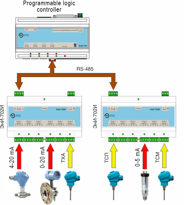
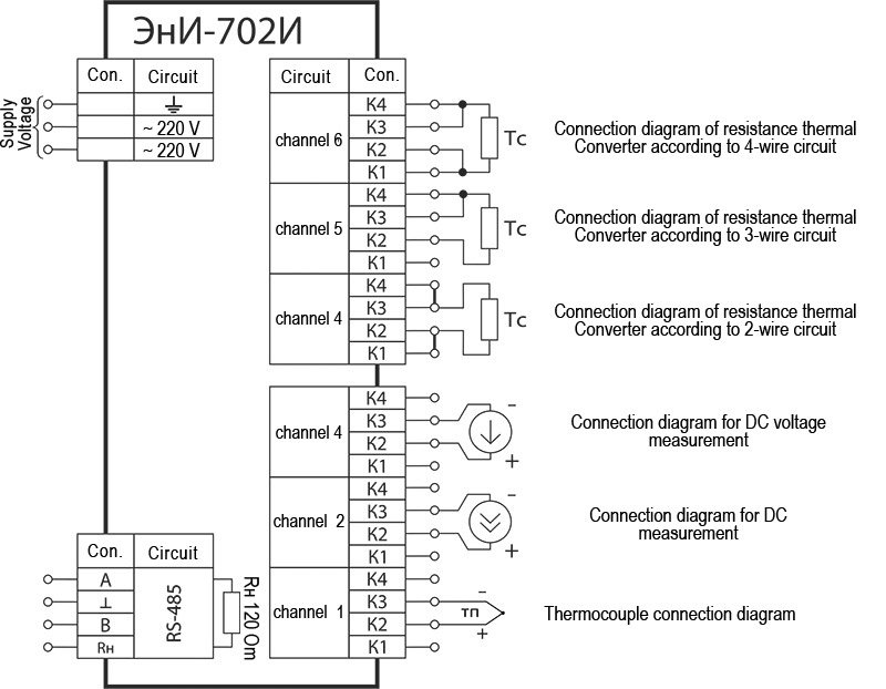
Measurement of AC intensity and voltage, resistance (including signal from thermal couples and resistance thermal converters. The measured value conversion into a digital code and its further transmission through the interface RS-485.

  • 6 universal, galvanically separated measurement channels;
  • Option of an individual measurement channel setting;
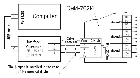
  • Data transmission interface is RS-485
  • Exchange protocol MODBUS RTU;
  • The programme to configure, archive and view the measured values on the PC is included in the contents of delivery;
  • Wide operating temperature range from -40 up to +50 °С.

Manufactured in accordance with the technical conditions EI.207.00.000 TC.

Использование Secondary equipment

Analog input module ЭнИ-702 And measures the signals:

  • from all main types of thermocouples according to GOST R 8.585;
  • from thermal resistance transducers according to GOST 6651 (connection scheme two -, three-or four-wire);
  • DC voltage in the range of 0...20 mV, 0...50 m V, 0...100 mV, 0...1000 m V;
  • DC current in the range of 0...5 mA, 4...20 mA, 0...20 mA;
  • resistances in the range 0...320 Om.

Used in various SCADA systems to convert analog signals from sensors of pressure, temperature, level gauges, flow meters etc in a digital code (MODBUS RTU Protocol) with the subsequent transfer of measured values via the RS-485 network.

For configuration of the six-channel measurement module ЭнИ-702И and PC is used the program «ЭнИ-702И Configurator, included in the package.

Example of PC connection

The connection of ЭнИ-702И to a personal computer

Example of connecting ЭнИ-702 To a personal computer

Example connection to a PLC

Example of ЭнИ-702И connection To a programmable logic controller

Example of ЭнИ-702 connection To a programmable logic controller

Example of operator panel connection

Connection example ЭнИ-702И the operator panel or indication panel of the ЭнИ-702

Connection example ЭнИ-702И the operator panel or indication panel of the Registrar ЭнИ-702

ЭнИ-702И functional scheme And

Functional diagram of the meter ЭнИ-702И

The power supply (ИП) converts the mains voltage supply of 220 V at 50 Hz into stabilized DC voltage required to supply the nodes of the normalizing Converter.

Input converters (ВП1...ВП) provide the conversion of the input signals from the sensors to the voltage, consistent with the range of input voltages of analog-to-digital converters (АЦП1...АЦП6). АЦП1...The АЦП6 converts the voltage from the outputs ВП1...ВП6 in digital code.

Module MP1...MP6 provide galvanic isolation of measurement channels from the microcontroller module (МКМ).

The channel switch (КК) will coordinate the ΜM control signals with the signals of the measurement channels.

The scheme of indication (СИ) indicates the modes of operation of the measurement channels on the LEDs.

МКМ control provides:

— survey of measurement channels;

— calculation of the current values of the measured parameters by the value of the codes АЦП1...АЦП6;

— ВП1…ВП6 control;

— control of the interface module (МИ). МИ provides galvanic isolation and coordination of levels of МКМ and RS-485 interface;

— communication via МИ via RS-485 interface with PC or other devices via MODBUS RTU Protocol;

—  The МКМ has a galvanic isolation with RS-485 interface circuits.

Key technical characteristics

Parameter Value
A.C. supply voltage range, V 110…265
A.C. supply voltage frequency, Hz 49…51
Power consumed from the A.C. main, В·А not more than 2
Time of operating mode setting, min not more than 15
Structural design plastic body frame to be mounted on a DIN-rail NS35\7,5
IP rating under GOST 14254 IP30
Average service life 12
Overall dimensions, mm not more than 160×88×60
Weight, kg not more than 0,3

Measurement channels

ЭнИ-702И contains six identical measurement channels galvanically separated from each other. Each of the channels can be separately configured for any type of a measured signal.

Parameter Value
Number of measurement channels 6
Measurement period (chosen by the customer), sec 0,1…10,0
Measurement averaging (number of measurements for averaging) 1…20
Device input resistance at the connection of the unified current signal source, Om 50
Device input resistance at the connection of the unified voltage signal source, kOm not less than 100
Connection diagram of thermal voltage converters (chosen by the user) 2-х, 3-х, 4-х
wire
Length of the connection line of resistance thermal converters at the line resistance of no more than 15 Om, m not more than 100
Length of the connection line of thermal couples at the line resistance (thermal electrode cable) of no more than 100 Om, m not more than 20
Length of the connection line of the DC voltage unified signal at the line resistance of no more than 5 Om, m not more than 100

Metrological characteristics

Primary converter type (sensor) Conventional symbol Measurement range,°С Range of the converter electromotive force change on НСХ, Оm2) δ1), %
50М, R100 / R0 = 1,42603) 50М-6 –50…+200 39,35…92,62 ± 0,2
53М, R100 / R0 = 1,4260 53М-6 41,71...98,17
100М, R100 / R0 = 1,4260 100М-6 78,70…185,20
50М, R100 / R0 = 1,4280 50М-8 39,23…92,80
53М, R100 / R0 = 1,4280 53М-8 41,38…98,34
100М, R100 / R0 = 1,4280 100М-8 78,46…185,60
50П, R100 / R0 = 1,3910 50П –50…+600 40,00…158,56
100П, R100 / R0 = 1,3910 100П 80,00…317,11
Pt100, R100 / R0 = 1,3850 Pt100 80,31…313,71
Primary converter type (sensor) Conventional symbol Measurement range, °С The range of measurements of EMF. Converter by НСХ, mV2) δ, %
ТЖК (J)4) ТЖК –50…+1100 –2,431…+63,792 ± 0,55)
ТХК (L) ТХК –50…+600 –3,005…+49,108
ТХА (K) ТХА –50…+1300 –1,889…+52,410
ТПП (S) ТПП 0…1700 0,000…17,947
ТПР (B) ТПР 300…1800 0,431…13,591
ТВР (A-1) ТВР 0…2500 0,000…33,640
Primary converter type (sensor) Conventional symbol Measurement range, мВ Input resistance, kOm, not less δ, %
Voltage U20 0…20 100 ± 0,2
U50 0…50
U100 0…100
U1V 0…1000
Primary converter type (sensor) Conventional symbol Measurement range Input voltage, mV, not more δ, %
Current I0-5 0…5 500 ± 0,2
I4-20 4…20 2000
I0-20 0…20 2000
Primary converter type (sensor) Conventional symbol Measurement range, Om Current through a measured resistance, mA δ, %
Resistance R320 0…320 0,2 ± 0,2

1) Limit of permissible basic percentage error.
2) Reference parameter.
3) R100 и R0 — resistance values from NSC at 100 and 0 °С, correspondingly.
4) Thermal couple types under МЭК 60584-3 are given in brackets.
5) With the account of the error of the cold junction temperature compensation.

Note — Compensation of cold junction temperature is provided within the ambient temperature range:
— from minus 30 up to plus 50 °С at the change of signals from thermal couples ТЖК (J), ТХК (L), ТХА (K) и ТПП (S);
—  from 0 up to 50 °С at the change of signals from thermal couples ТПР (B), ТВР (A-1).

Communication interface

Эни-702I configuration is possible with the PC help, ЭнИ-702 indication panel or any other device through the interface RS-485.

Parameter Value
Interface exchange rates, kbit/sec (chosen by the user) 2,4; 4,8; 9,6; 19,2; 38,4; 57,6; 115,2
IP address range (chosen by the user) 1…247
Exchange protocol MODBUS RTU
Cable length, m not more than 1200

For the operation as a terminating device there is a built-in load resistance of 120 Om Recommendations on Layout of Main RS-485.

Overall dimensions

Overall dimensionsы

1 — DIN-rail;
2 — warranty label;
3 — connector 2EDGK-5.0-04P to connect the interface RS-485;
4 —LED "Supply";
5 — connector 2EDGK-5.0-03P to connect supply-line voltage;
6 — LEDS indicating measurement channels state control;
7 — connectors 2EDGK-5.0-04P to connect the sensors.

Indication modes

Event LED
«Power supply» «Channel 1…6»
ЭнИ-702И is off
ЭнИ-702И is on, channel/channels are off +
ЭнИ-702И is on, channel/channels are off + +
ЭнИ-702И is on, channel/channels are off, signal level on the channel/channels input fell outside the permissible limits + +/– 1 Гц
ЭнИ-702И is on, channel/channels are on, tripping of break-wire sensor of the thermal couples, resistance temperature device or resistance channel/channels + +/– 0,5 Гц

Notes:
—  «+» — light on;
— «–» — light off;
— «+/– 1 Hz» — flashes with the frequency 1 Hz;
— «+/– 0,5 Hz» — flashes with the frequency 0.5 Hz.

Measurement channel connection diagram

 Measurement channel connection diagram ЭнИ-702И

Note — Any of six channels can be configured to connect any sensor type.

RS-485 interface connection diagram to a PC

RS-485 interface connection diagram to a PC

Notes:
— connection to the PC USB-port is provided through the USB interface converter — RS-485. Interface Converter Эни-40 can be supplied by the order;
— the circuit is given to connect one ЭнИ-702И. At the connection of several ЭнИ-702И it is necessary to follow the rules for the RS-485 interface layout.

Connection diagram by the interface RS-485 k of the indication panel ЭнИ-702

Connection diagram by the interface RS-485 k of the indication panel ЭнИ-702

Note — The circuit is provided to connect one Эни-702I. At the connection of several Эни-702I it is necessary to follow the rules for the RS-485 interface layout.


Parameter Value
Ambient temperature, °С -40…+50
In terms of climatic effect resistance at operation corresponds to the version group, under GOST R 52931 С3
In terms of mechanical impact resistance at operation corresponds to the version group, under GOST R 52931 L3
Ingress protection level, under GOST 14254 IP30

Warranty liabilities

Parameter Value
Warranty operating life, months 36 months since the commissioning date but no more than 42 months since the date of manufacture

Contents of delivery

Name Designation Number Note
Six-channel measurement modules ЭнИ-702И   1 in compliance with the order

Data Sheet

Operation manual

  1  
Terminal board (4 contacts) 2EDGK-5.0-04P 7  
Terminal board (3 contacts) 2EDGK-5.0-03P 1  
Disc with software   1  
DIN rail NS35\7,5   by order
Interface converter ЭнИ-402     by order

Designations at the order

ЭнИ-702И 360
1 2

1. Name.

2. Additional technological no-failure operating time up to 360 hours.

Six-channel measurement modules Эни-702I

Six-channel measurement modules Эни-702I
wait Item successfully added.
Proceed to checkout?
1000 characters left
Обработка персональных данных включает согласие с Пользовательским соглашением и Политикой конфиденциальности и Вы принимаете их условия.