Three-channel current meters ЭнИ-703И

1000 characters left
Обработка персональных данных включает согласие с Пользовательским соглашением и Политикой конфиденциальности и Вы принимаете их условия.

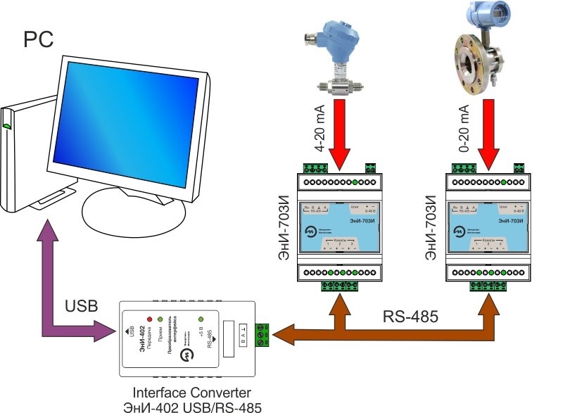
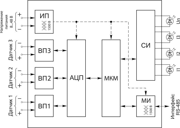
D.C. Intensity and voltage measurement in the ranges 0...5 mA, 4...20 mA, 0...20 mA. The measured value conversion into a digital code and its further transmission through the interface RS-485.

  • 3 channels to measure unified signals 0…5, 0…20, 4…20 mA;
  • Option of an individual measurement channel setting;
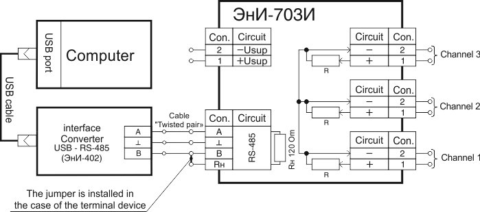
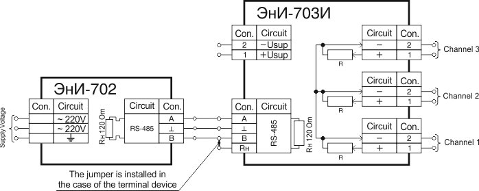
  • Data transmission interface is RS-485
  • Exchange protocol MODBUS RTU;
  • The programme to configure, archive and view the measured values on the PC is included in the contents of delivery;
  • Wide operating temperature range from -40 up to +50 °С.

Manufactured in accordance with the technical conditions EI.207.00.000 TC.

Использование Secondary equipment

МThe analog input module ЭнИ-703И is used in conjunction with a programmable logic controller or with a personal computer integrated into the SCADA system to convert analog signals (unified current signals) from pressure sensors, temperature, level meters, flow meters, etc.into a digital code with the subsequent transmission of the measured value via the RS-485 interface(MODBUS RTU Protocol).

To configure the three-channel measurement module from a PC, the Eni-703 program and the Configurator included in the delivery are used.

Example connection to a PLC

Connection of ЭнИ-703И to the programmable logic controller

Connection example ЭнИ-703И to a programmable logic controller

Example of PC connection

The connection of ЭнИ-703 And to a personal computer

Connection example ЭнИ-703И to a personal computer

Example of operator panel connection

Connect ЭнИ-703И the operator panel or indication panel of the Registrar ЭнИ-702

Connection example ЭнИ-703И the operator panel or indication panel of the Registrar ЭнИ-702

Functional diagram ЭнИ-703И

 Functional diagram ЭнИ-703И

The power supply (ИП) converts the external supply voltage 8...48 Into a stabilized DC voltage required to supply the nodes of the normalizing Converter.

put converters (ВП1...ВП3) provide conversion of values of input current signals in the voltage, agreed on the range with the input voltage of the analog-to-digital Converter (АЦП). The АЦП converts the voltage from the outputs of ВП1...ВП3 into a digital code.

The indication circuit (СИ) indicates the modes of measurement channels on the LEDs.

Microcontroller control module (МКМ) provides:

  • — survey of measurement channels;
  • — calculation of the current values of the measured parameters by the value of the АЦП codes;
  • — control of the interface module (МИ), MI provides galvanic isolation and coordination of levels of МКМ and RS-485 interface;
  • — ommunication via МИ via RS-485 interface with PC or other devices via MODBUS RTU Protocol;
  • — The МКМ has a galvanic isolation with RS-485 interface circuits.

Key technical characteristics

ParameterValue
D.C. supply voltage range, V 8…48
Consumed power, W не более 2
Time of operating mode setting, min не более 15
Structural design plastic body frame to be mounted on a DIN-rail NS35\7,5
IP rating under GOST 14254 IP30
Average service life 12
Масса, кг not more than 0,1

Measurement channels

ЭнИ-703I contains three identical measurement channels galvanically separated from each other (negative common). ЭнИ-703I has galvanically separated input electric circuits, interface lines RS-485 and a power supply source.

ParameterValue
Number of measurement channels 3
Measurement period (chosen by the customer), sec 0,1…10,0
Measurement averaging (number of measurements for averaging) 1…20
Device input resistance at the connection of the unified current signal source, Om 50

Measurement ranges

Measurement range, mAConventional symbolInput voltage, mV, not more
0…5 I0-5 500
4…20 I4-20 2000
0…20 I0-20 2000

Metrological characteristics

ParameterValue
Limit of permissible basic percentage error, % ± 0,1
Limits of permissible complementary error induced by the ambient temperature change from a normal value up to any temperature within the operation temperature range for every 10 °С, % not more than the limits of permissible basic percentage error, %
Limits of permissible complementary error caused by high humidity action,%
Limits of permissible complementary error caused by the supply voltage change in the operating range,%
Setting time within which the measured value is included into the zone of permissible basic percentage error, sec (at the change of measurement period of 0.1 sec and measurement averaging 10) not more than 1

Communication interface

ЭнИ-703И configuration is possible with the PC help, ЭнИ 702 indication panel or any other device through the interface RS-485.

ParameterValue
Interface exchange rates, kbit/sec (chosen by the user) 2,4; 4,8; 9,6; 19,2; 38,4; 57,6; 115,2
IP address range (chosen by the user) 1…247
Exchange protocol MODBUS RTU
Cable length, m not more than 1200

For the operation as a terminating device there is a built-in load resistance of 120 Om. Application recommendations.

Overall dimensions

The dimensions of the ЭнИ-703И

1 - DIN rail; 
2 - warranty label; 
3 - connector 15EDGK-5.08-04P for connecting the RS-485 interface. 
4 - LED "Usup" availability of supply voltage; 
5 - connector 15EDGK-3.81-02P for connecting the supply voltage; 
6 - "1 ... 3" LEDs for monitoring the status of measurement channels; 
7 - connectors 15EDGK-5.08-02P measuring channels for connecting sensors.

Indication modes

EventLED
«Uп»«channels I1…I3»
ЭнИ-703И is off
ЭнИ-703И is on, channel/channels are off +
ЭнИ-703И is on, channel/channels are off + +

Примечания:

— «+» — light on;

— «–» — light off.

Scheme for connecting measuring channels to sensors with active current output

Scheme for connecting measuring channels to sensors with active current output


Scheme for connecting measuring channels to sensors with passive current output

Scheme for connecting measuring channels to sensors with passive current output


RS-485 interface connection diagram to a PC

RS-485 interface connection diagram to a PC

Notes:

— connection to the PC USB-port is provided through the interface converter USB — RS-485. The interface converter ЭнИ-402 can be supplied by the order;

— the circuit is provided to connect one ЭнИ-703I. At the connection of several ЭнИ-703I it is necessary to follow the rules for the RS-485 interface layout.


Connection diagram by the interface RS-485 k of the indication panel ЭнИ-702

Connection diagram by the interface RS-485 k of the indication panel ЭнИ-702

Note — The circuit is provided to connect one ЭнИ-703I. At the connection of several ЭнИ-703I it is necessary to follow the rules for the RS-485 interface layout.


ParameterValue
Ambient temperature, °С -40…+50
In terms of climatic effect resistance at operation corresponds to the version group, under GOST R 52931 С3
In terms of mechanical impact resistance at operation corresponds to the version group, under GOST R 52931 L3
Ingress protection level, under GOST 14254 IP30

Warranty liabilities

ParameterValue
Warranty operating life, months 36 months since the commissioning date but no more than 42 months since the date of manufacture

Contents of delivery

NameNotationamountNote
Three-channel current meter EnI-703I EI.211.00.000 1 according to the order

Passport Instruction Manual

EI.211.00.000PP 1  
Bracket (2 pins) 15EDGK-3.81-02P 1  
Bracket (2 pins) 15EDGK-5.08-02P 3  
Bracket (4 contacts) 15EDGK-5.08-04P 1  
CD with software   1  
DIN rack NS35 \ 7,5   by order
Interface converter EnI-402     by order


Designations at the order

ЭнИ-703И360
1 2

1. Name.

2. Additional technological no-failure operating time up to 360 hours.

Three-channel current meters ЭнИ-703И

wait Item successfully added.
Proceed to checkout?
1000 characters left
Обработка персональных данных включает согласие с Пользовательским соглашением и Политикой конфиденциальности и Вы принимаете их условия.